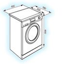
Error code F06 in a Hisense washing machine
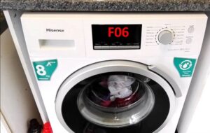 The F06 error in a Hisense washing machine is caused by a problem with the main electronic module. The washing machine simply freezes and displays an error code. First, try resetting your "home assistant"—this will help in the event of a short-term system failure.
If the error persists after rebooting, you'll need to diagnose the control board. Such complex work is best left to professionals. However, you can rule out certain problems yourself, at home.
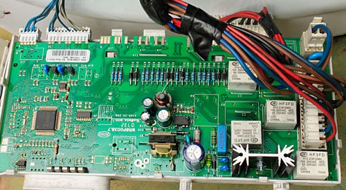
Elements of the control board and their purpose
The electronic module is one of the most expensive components in Hisense washing machines. Repairing the board yourself without the necessary skills is risky. The risk of not fixing it and only making the situation worse is high.
It is recommended to entrust diagnostics and repair of the washing machine's main control module to professionals.
The module's design is very complex—not every user can understand the purpose of all the semiconductors and traces. Therefore, it's best to consult with professionals. Service center technicians will test the board with specialized equipment, repair the unit, and if repair is impossible, replace the microprocessor.
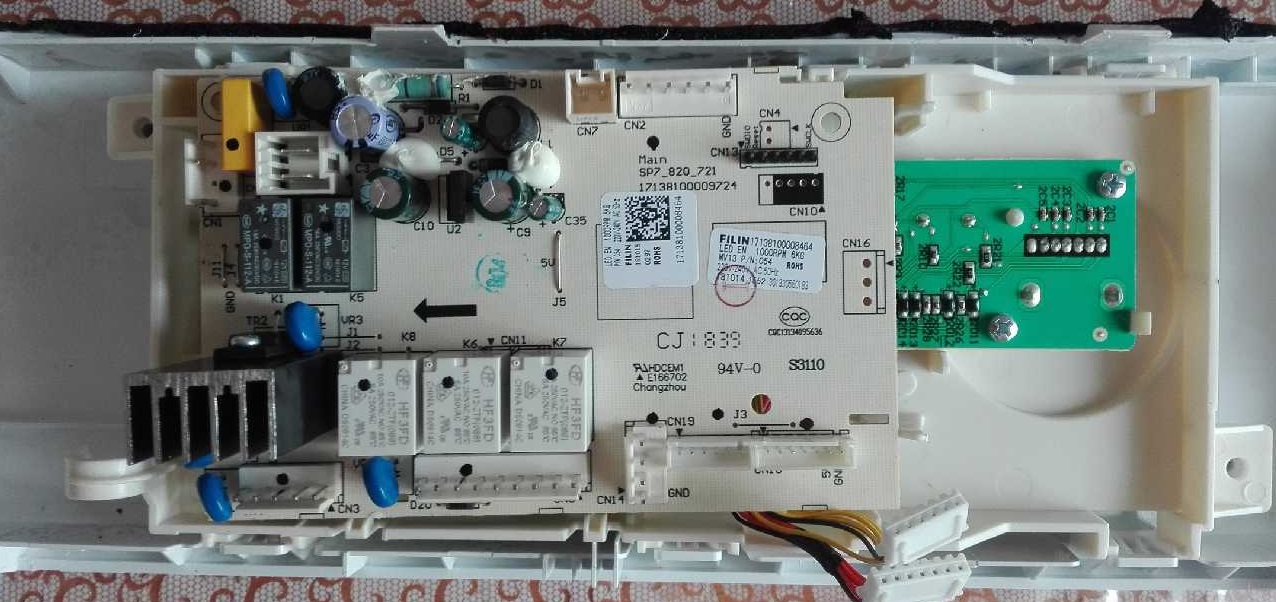
If you decide to repair your Hisense washing machine module yourself, be prepared. First, familiarize yourself with its structure. The component consists of:
- control panels;
- power unit.
Using buttons and switches on the control panel, the user gives commands to the machine's "brain." Then the power unit is activated, sequentially activating the remaining components of the washing machine.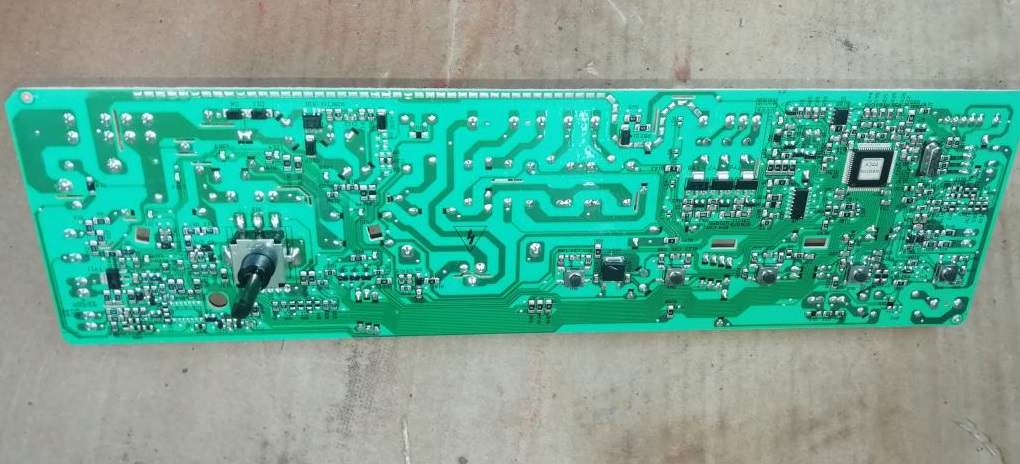
The control board contains semiconductor components. Each section is responsible for the operation of specific components of the washing machine. The left-hand module contains semiconductors that coordinate the washing machine's power supply. These are:
- integrated stabilizer KIA7805, designated U14;
- pulse converter based on the STR-A6059M PWM controller;
- network rectifier and filter (designations BD1 and CE4);
- protective varistor (Z2);
- network fuse;
- key converter microcircuit (U12);
- SMPS pulse transformer;
- diode D13, capacitor CE2;
- diode D11, capacitor CE8, power supply channel 9V;
- diode D12, capacitor CE9, power supply channel 12V;
- diode D14, capacitor CE6, power supply channel 12V;
- diode D6, zener diode ZD1, transistor Q1, resistor R103;
- resistor R74, aka 205;
- optocoupler U15, transistor assembly U3;
- U13 processor;
- relay X1 (it is also connected in series to the heating element circuit);
- integrated voltage stabilizer 5V, (marked U).
The next section of the board is responsible for the temperature sensor. This unit consists of the following semiconductor components:
- pin 4 (TH1) of the RD6 combiner;
- resistor R12;
- 37 microprocessor leg U.
The following semiconductors on the control board are responsible for the operation of the heating element of the Hisense washing machine:
- relay X1;
- 64 pin of U13 processor;
- 1 and 16 legs of U3 assembly;
- relay X2;
- 24 leg of U13 processor;
- transistor Q7.
The power unit has a spare relay control channel. Its components are installed optionally. What semiconductors are involved:
- 75 leg of U13 processor;
- resistor R83;
- transistor Q5;
- relay X4;
- the second terminal of the BL connector.
The operation of the water level sensor is controlled by the following elements of the unit:
- resistors R6, R7;
- 67 leg of microprocessor U13.
The next section of the board controls the pre-wash compartment inlet valve. These semiconductors start and stop the water intake specifically for this compartment of the detergent drawer. These components include:
- 29 leg of U13 processor;
- 4 and 13 legs of U3 assembly;
- resistor R25, R29;
- optocoupler U8;
- triac TR3;
- contact 1 of connector YL4.
Next are the semiconductors that control the operation of the electromagnetic valve in the powder compartment for the main wash. These are:
- 31 legs of U13 processor;
- 6 and 11 legs of U3 assembly;
- resistor R23, R27;
- optocoupler U6;
- triac TR5;
- pin 4 of YL4 connector.
Next comes the circuit responsible for the operation of the hot water inlet valve. It consists of the following components:
- 31 legs of U13 processor;
- 6, 11 legs of U3 assembly;
- jumper J1;
- resistor R24, R28;
- optocoupler U7;
- triac TR4;
- the second terminal of the YL4 connector.
What components are responsible for the operation of a drainage pump? We are talking about:
- 61 legs of controller U13;
- resistors R77, R79, R82;
- transistors Q4, Q3;
- optocoupler U4;
- triac TR20;
- contact 4 of connector BL4.
Another section of the module operates the hatch locking device. This is a semiconductor unit:
- 27 leg of U13 processor;
- 2 and 15 legs of U3 mesh;
- R21;
- optocoupler U2;
- relay X3;
- contact 1 of connector BL4.
The following are responsible for the functioning of the tachometer sensor:
- contacts 4 and 6 of connector BL6;
- resistor R44, R60;
- contacts 3, 4, 5, 6 from U1;
- 19 and 20 leg of block U.
Now let's talk about the section responsible for the electric motor's operation. These elements are:
- 17 leg of block U13, power circuit HS1 (output stages and drivers), microcircuit U1;
- comparator from the circuit U11, choke RA, a pair of resistors R58 and R57;
- 6 and 7 contacts of comparator U11, voltage stabilizer 300V, diode BD1, resistor R70 and 41, processor leg U.
The board also contains resistors R73, R72, 73, and 74, as well as processor pin U13. These elements control the program selector.
Each semiconductor block on the control module is responsible for the operation of certain parts of the Hisense automatic washing machine.
The module has many components. Figuring out why the unit has stopped working and is displaying a fault code is difficult, especially for a beginner. Without having an idea of what resistors, optocouplers, relays, and comparators are, it is better not to disassemble the microcircuit. If you have some electronics skills, you can diagnose the board yourself.
How to check board components?
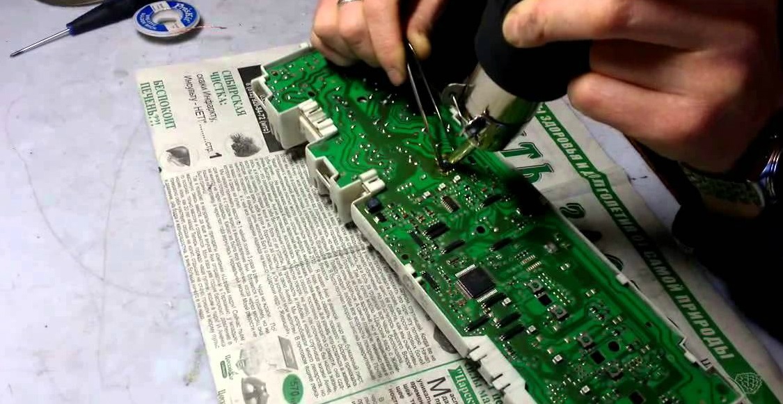
Diagnosing the unit isn't easy. Firstly, the component is encapsulated in compound. Secondly, the board is protected by a shroud, which will also need to be removed. Here's how to proceed:
- remove the sealant from the outer edges of the module; to do this, use a thin screwdriver to go along the inner perimeter of the casing;
- deepen the recess around the perimeter of the board in the gap between the control module and the casing;
- place a screwdriver between the casing and the block, where the transformer is visible;
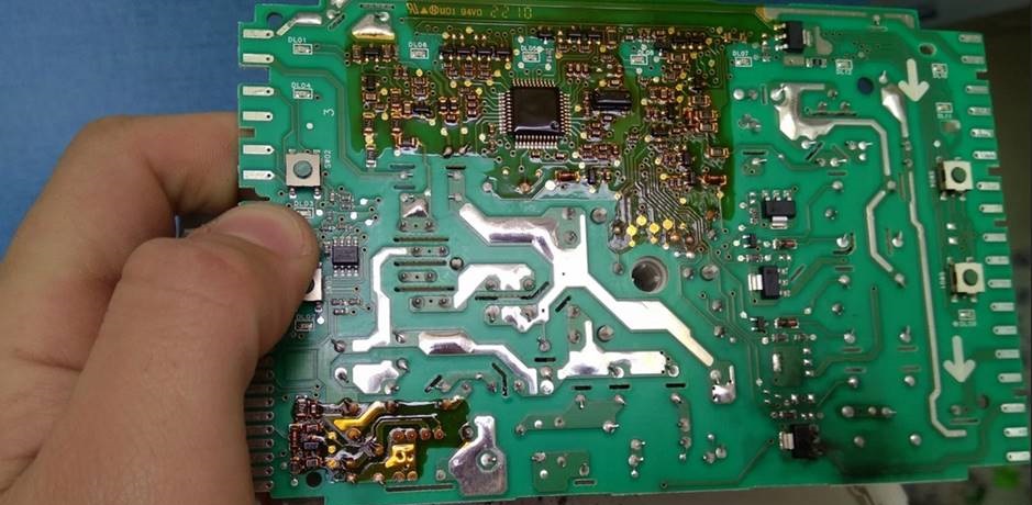
- Using careful lifting movements, remove the block from the casing;
- clean the board;
- proceed with diagnostics;
- repair the damaged section of the block (usually it is soldered out and replaced completely);
- Cover the board with protective varnish (Plasik70 for assembly work).
Experienced technicians do not remove the protective cover entirely, but cut a hole in it, gaining access to the damaged area of the board.
This work must be performed with extreme care. Removing the unit from the housing carries a high risk of damaging the microprocessor. Therefore, users are advised not to attempt to repair the module themselves.
Interesting:


Readers' comments
Headings
Washing machine repair

For buyers
For users

Dishwasher
Add a comment