Checking the washing machine's triac
 The washing machine's control board is littered with semiconductor devices called triacs. Sometimes, one or more of these elements burn out, rendering the machine unable to function properly. Visually identifying burned-out components is quite difficult for the average user, so diagnostics of the module are required.
Of course, whenever possible, it's best to entrust electronic repairs to professionals. If you want to test the triac in your washing machine yourself, you need to be well prepared and understand all the nuances of the upcoming work. We'll explain how semiconductors are tested.
How can I test the parts?
There are several ways to check the control board of an automatic machine. Technicians most often perform diagnostics of the electronic module using a multimeter, a transistor tester, or a special stand. At home, DIYers sometimes test triacs using a regular light bulb and a battery.
The most convenient and easiest way to test the triac in a washing machine is with a multimeter.
If you don't have this measuring device at home, you can buy one at any specialty store. Multimeters are inexpensive—from $2 to $3 and up. An inexpensive model is also suitable for home use.
Thyristors and their typical problems
To understand how to test triacs, you need to understand the design features of these components. These are semiconductors that constantly open and close during operation. They allow electric current to flow in both directions.
In terms of the design of a triac, it consists of two crystals facing each other and a control electrode. The latter ensures the opening and closing of the semiconductor. Due to this design, these elements are considered a type of thyristor.
A break in the triac circuit may occur, or the element may burn out due to a short circuit. If you plan to test the semiconductor with a multimeter, there are two ways to do it:
- with soldering of the triac;
- directly on the control board.
The second method is much more convenient because it allows you to test the semiconductor device without any additional manipulation of the electronic components. However, the overall performance of the electronic module will also affect the results of this diagnostic. Therefore, it is advisable to test the triac by desoldering it from the board – this will improve the accuracy of the test.
When testing on a board, a short circuit in a parallel line can affect the results. In this situation, the multimeter will indicate a faulty triac, while the problem is not with this semiconductor device at all.
Test with the triac separated from the board
The most accurate diagnostic results will be achieved by desoldering the triac from the control board and testing it separately. Testing an independent component will yield more accurate readings from the multimeter. If you choose this diagnostic method, you need to determine the orientation of the semiconductor's terminals or "legs." There are several types of triacs, and the image below shows just a few.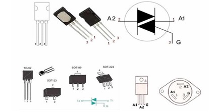
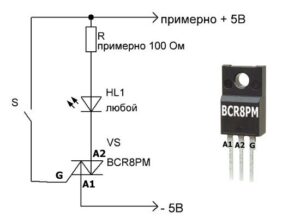
It is necessary to determine the location of the control contact of the triac in relation to the pair of power terminals.
It's important to know the contact layout in advance. You can find out which pin is which using the semiconductor model or datasheet. This is crucial for further diagnostics.
The structure of semiconductor elements is similar. Any triac has 3 contacts - two power and one control. The working pair of terminals is usually marked A1 and A2 (sometimes T1 and T2). The remaining one is marked with the English letter G.
Once you've grasped the triac's design, you can begin setting up the multimeter. The tester should be set to "continuity" mode. The vast majority of these devices have a dedicated button that needs to be turned on. The button is marked with a diode and a buzzer (simulating a sound signal).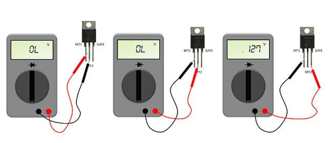
After setting the multimeter to "continuity" mode, place its probes on the corresponding terminals of the triac. A potential difference will appear between the tester's leads, as voltage will be applied to them. The device will ensure that the test current "flows" through the semiconductor. Diagnosing the control board element is carried out in several stages.
- Step 1. Place the multimeter probes against the power contacts. If the device displays 1 or "OL," the triac is functioning properly. A zero on the tester display indicates a breakdown of the semiconductor.
- Step 2. One multimeter probe remains on the working terminal, and the other is connected to the control terminal. Normally, the tester screen should display a value between 100 and 200 V, though slight variations are acceptable.
- Step 3. Verify that the triac is conducting. To do this, quickly touch the control electrode while continuing to apply voltage to the active terminals. The readings on the multimeter display should immediately change. If the readings adjust, the semiconductor is functioning properly.
To connect the multimeter probes to both "legs" of the triac at once, you can use additional wiring.
If no faults are detected during testing of the desoldered triac, the problem lies not with it, but with another semiconductor on the control board. You'll need to continue the diagnostics and test all the module's components and traces one by one.
Interesting:


1 reader comment
Add a comment
Headings
Washing machine repair


For buyers


For users


Dishwasher


Where can I buy a washing machine control module?