Reverse gear on a washing machine motor
 According to statistics, the most serious washing machine breakdowns are electronic module failure and bearing wear. Other malfunctions, while more common, are easily remedied. Even if your washing machine is hopelessly broken, its "heart," the motor, usually continues to function properly and can be reused.
That's why a washing machine motor is often used in the construction of various machines, such as grinders, lathes, and so on. To ensure proper operation of this homemade device, the washing machine motor needs to be reversed. Let's figure out how to do this yourself.
Let's gather everything we need
Connecting the electric motor and reversing it will require specialized equipment and tools. A standard multimeter will be useful for checking the electrical circuit. A tester can be purchased at specialized stores.
In addition, the following will be required during the process: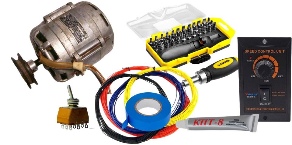
- toggle switch (electric current switch) 220 Volts, 15 Amps;
- engine speed controller;
- wires of different colors (it is recommended to use blue (neutral) and brown (phase));
- the electric motor itself (the motor from any old automatic washing machine will do);
- insulating tape;
- screwdrivers;
- packaging of thermal paste.
Of course, you'll also want to have other materials on hand to construct your homemade device. Once you've got everything ready, you can get to work.
Powering the motor
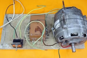
First, carefully examine the dismantled electric motor. The collector usually has 6 terminals: two for connecting the tachometer and a pair of wires for the stator and rotor windings. The tachogenerator is of no use outside the washing machine, so these contacts can be immediately discarded.
To power a single-phase motor, it is necessary to connect the output of the stator winding and the beginning of the rotor winding, and connect the other ends to the neutral contact and the phase.
To determine the winding terminals on the plug, you'll need a multimeter. Place one tester probe on the terminal, and then touch the other terminals one by one. If the ohmmeter indicates a short circuit, then both terminals are connected to the same winding.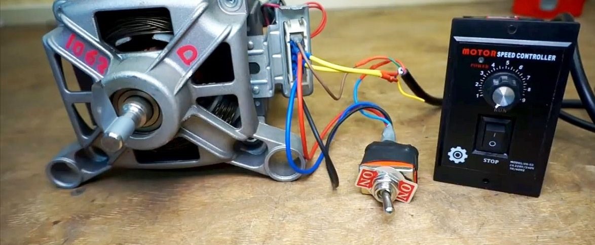
Once everything is in order, you can apply standard 220-volt power to the motor. Under normal circumstances, the motor will start and rotate in one direction—either counterclockwise or clockwise.
How to ensure reverse rotation?
Reversing an electric motor is the reversal of the rotor's direction of rotation. To achieve this, the ends of one of the windings must be reversed. This causes the motor to rotate in the opposite direction.
To avoid constantly messing with the circuit and rearranging the winding wires, it is better to install a special device. The direction of rotation of the rotor can be switched by clicking the toggle switch. The connection is easy to do yourself.
First, flip the switch over and examine the markings on the bottom of the device. They show the designations of all the outputs, as well as a wiring diagram for different switch positions (left and right). To make it easier to understand, draw a basic circuit: two motor windings and a pair of switch contacts. The middle wires are connected alternately to the side wires.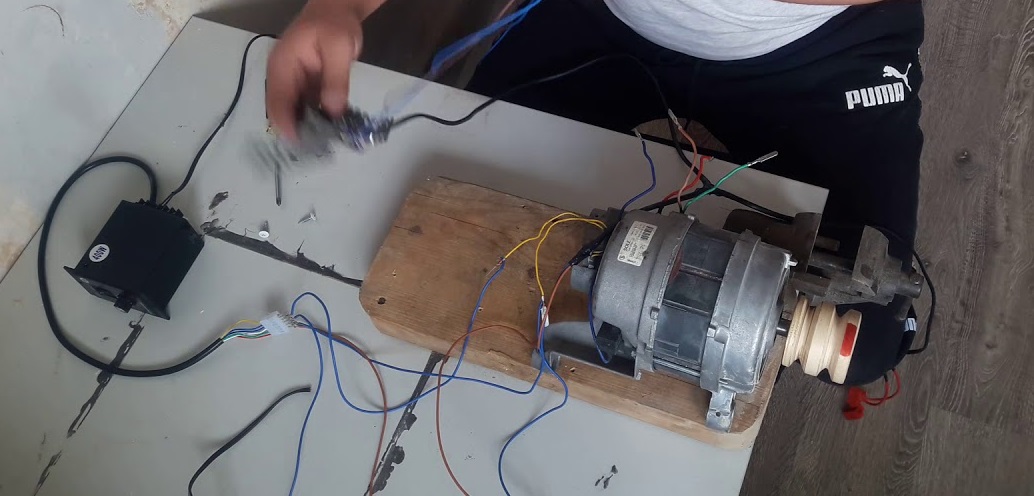
The terminal of one winding must be connected to the bottom contact located at the edge and connected with a jumper to the outer terminal located at the top. The stator winding wire must be connected to the connector located in the middle.
Now all that's left to do is connect the rotor to the circuit. Connect the rotor winding output to one terminal of the switch, and the neutral supply wire to the other, remaining terminal. After that, diagonal jumpers must be installed between the two outer terminals. The first middle terminal of the toggle switch is connected to the neutral terminal, and the second to the rotor winding tail.
Once you have completed the circuit, be sure to check that all contacts are connected correctly.
In short, the middle contacts of the mechanical switch must be connected: one to the neutral wire, the other to the stator winding. The opposite "tail" of this winding is connected to the live wire (the brownish wire). It is essential that the diagonal contacts be connected with jumpers, and the wires from them be routed to the rotor winding.
Before starting the motor, equip yourself with a multimeter. Use a tester to check how the short circuit changes when you click the switch. Be sure to insulate all contacts. The motor's rotation direction can only be changed once the rotor has completely stopped. Therefore, don't rush to click the switch; wait until the element stops spinning.
How to increase and decrease engine speed?
You can order a motor speed controller on the well-known website AliExpress. Keep in mind that cheap products from China don't always live up to the quality claims, so be sure to inspect the device. Remove the internal components from the housing and carefully inspect the triac. If you're lucky, it will have a small heatsink that barely manages to prevent overheating. In the worst case, there won't be any heatsink at all, in which case you'll have to purchase the part separately.
You'll need to cut an M3 thread on the "imperfect" heatsink. Then, apply a small amount of thermal paste to the surface of the triac and secure the upgraded heat exchanger in place. Then reassemble the controller.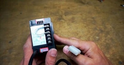
On the back of the device is a strip with several connectors and terminals. All the terminals are labeled. You need to find the neutral, phase, and ground terminals, and connect the corresponding cables to them.
The top panel of the speed controller housing should indicate the purpose of each output and the corresponding wire color.
Typically, the yellow output wire is ground, the pair of blue ones are the tachometer terminals, and the bright red one is the live terminal. The white and green contacts are interchangeable, which is controlled by a jumper. You can determine the resistance of the terminals by testing them with a multimeter.
Once you've figured out how to use the device, connect it to the engine. Make sure the wires are connected to the appropriate terminals. Once you're done, apply 220V power to the electric motor speed controller. Now you can easily change the engine speed and rotation modes manually.
The controller also has a special opening on its sides. It's designed to adjust the electric motor's operating modes using a variable resistor. You can set the motor speed increment. This way, when the circuit starts, the rotor rotation will not be jerky, but will begin smoothly, practically from zero.
Interesting:


")


Readers' comments
Headings
Washing machine repair

For buyers

For users


Dishwasher
Add a comment