The triac in the washing machine burned out.
 It's easy to suspect a burned-out triac in a washing machine—the machine freezes, won't turn on, or operates with obvious malfunctions. However, it's impossible to be 100% certain that a faulty electronic component is at fault, as other electronic malfunctions can also exhibit similar symptoms. To confirm the diagnosis, a comprehensive diagnostic of the washing machine's control board is necessary.
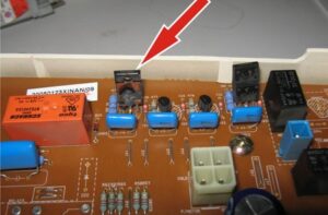
The electronic module should be dismantled, inspected, and, once the triacs are located, testing them begins. Let's look at what to do and in what order.
Methods for testing triacs
Before repairing and replacing the triac on the control board, it is necessary to make sure that the semiconductor is faulty. There are different ways to test a radio element. The following verification options are most commonly used:
- “continuity” with a multimeter;
- installation on a test bench;
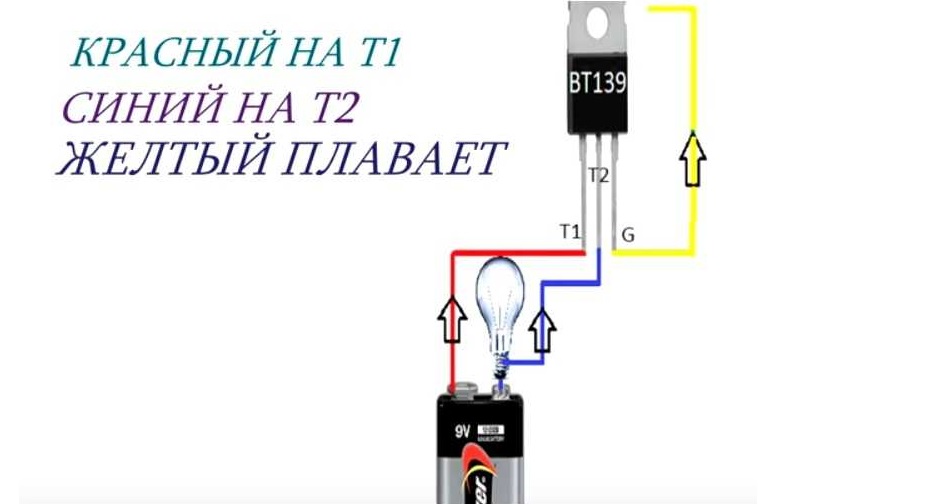
- connection to a circuit with a power source and a lamp;
- examination with a transistor tester.
To test the triac on the control board, it is enough to have a multimeter at hand.
The most popular way to diagnose a triac is to test it with a multimeter. Unlike a transistor tester, this type of tester is readily available and fairly easy to use. However, setting up a test bench or setting up a test circuit for a one-time check is more difficult and time-consuming. It's best to keep things simple and opt for a multimeter.
Typical failures of these parts
Before diagnosing a triac, it's recommended to understand its design and operating principle. From an electrical engineering perspective, it's a semiconductor that opens and closes to allow current to flow, similar to a thyristor. However, unlike the latter, this electronic component consists of two crystals connected in parallel, allowing it to conduct current pulses in both directions. This feature makes it widely used in AC voltage systems.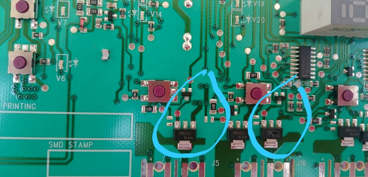
The triac can fail for two reasons:
- a circuit in the semiconductor was broken, with subsequent disruption of its integrity;
- a pn junction breakdown occurred, in simple terms, a current leak.
The triac on the board fails when the line is broken or when the p-n junction is broken.
Even a professional electrician won't be able to detect a problem with a triac without using a multimeter—everything might appear "clean" visually. To confirm the semiconductor's fault, you'll need to use a buzzer and measure the resistance at the contacts.
We test the part according to the instructions
Before proceeding with direct testing, you should decide on the diagnostic method. There are two options: either desolder the semiconductor and test it separately, or carry out measurements directly on the board. The second method is simpler, more convenient, and safer: it eliminates the need for unnecessary manipulation, reducing the likelihood of errors and further escalation. However, it does have a drawback: the overall performance of the module will inevitably affect the results, throwing them off.
To obtain an accurate result, desolder the triac from the board before connecting the multimeter probes. It is recommended to follow the instructions strictly.
- Determine the location of the control contact and the two working contacts. Ideally, you should study the electrical diagram of the component. If the data sheet is unavailable, consult the triac model. Any such electronic component has three electrodes. Two of them are power electrodes and are marked with the combination "A1" and "A2" or "T1" and "T2." The third pin is the main pin and is designated by the letter "G" (from "gate"). It is important to determine which pin is located on the semiconductor.
When desoldering the triac from the control board, be careful not to damage adjacent elements and tracks!
- Set up the multimeter. You need to activate the buzzer mode to test for breakdown. On most modern testers, this is indicated by a button with a picture of a semiconductor diode.
- Connect the multimeter clamps to the appropriate sockets. This is the socket marked "COM"—the common relay, designed for measuring resistance and testing for breakdown. This creates a potential difference across the ends of the tester probes, and the operating current and test voltage are supplied to the triac being tested.
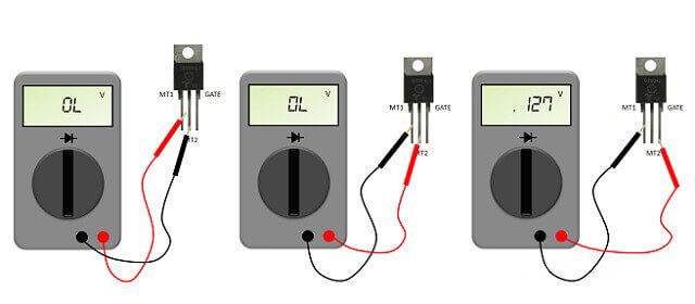
Once the triac and multimeter are ready, you can begin diagnostics. First, the junction is tested for breakdown: the probes are placed against the power electrodes, and the result is evaluated. A "0" indicates a faulty component. If the display shows a "1," the semiconductor is operational. Some modern testers display "OL" instead of "1," which also indicates the component is working properly.
The second step is to move one of the probes to the control contact to measure the resistance between them. Normally, the reading should differ by approximately 100-200 ohms. Then, connect the clamp to the other power electrode, which will result in a "1" display on the screen.
Next, we check whether the radio element's transition opens. To do this, quickly touch the control terminal with the probe while applying current to the other contacts. This can be achieved by using an additional wire or by placing the tester clamp diagonally. If the triac is working properly, the reading on the multimeter screen will change – a different number will appear instead of one. It is important to be extremely careful, since the semiconductor will not remain in the open state for long due to insufficient voltage.
If the test reveals that the removed triac is working properly, then another component on the control board is causing the problem. For a comprehensive module diagnosis, it's best to contact a service center.
Interesting:


Readers' comments
Headings
Washing machine repair


For buyers


For users


Dishwasher


Add a comment